Thursday, December 30, 2010

CV joints for the Odyssey

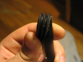
After getting the tires replaced on the 1998 Honda Odyssey, the service man mentioned that the CV joints were clicking, particularly on acceleration, and would we like to set up an appointment to get them replaced? After politely declining, we headed home, listening for the clicking he had heard. I didn't hear any noise, but I had noticed the "clunk" when shifting into drive, as the transmission took up the slack in the loose joints.
So I Googled CV Joints, and it turns out they are only $50 each from RockAuto. They arrived shortly before Christmas, in the middle of a snowstorm, so I waited until yesterday to install them.

Having never done them before, I got an impromptu tour of the internet how-tos on CV joint replacement...... Pretty slim pickings. Notes I made:

-        Rent a 36mm axle nut socket from AutoZone. You also need a breaker bar if you don’t have one.
-        Loosen the lugs and the axle nut while the wheel  is on the ground providing resistance.
-        You need a new axle nut for each side, also called a stake nut. Don’t buy them separately if they came on the new CV joints......
-        You need a Pitman arm puller, about $12 at AZ.
-        No matter what the internet guides say, DO NOT PULL on the CV to get it out. It probably won’t work, and it ruins the CV joint, in case you had removed it for other reasons.
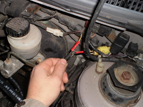
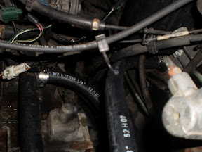
-        Get under there and PRY it out of the tranny. One side was easy, the other incredibly hard.
-        If you hear a scraping noise on the test drive, it just might be that brake rotor shield you pulled on so hard when you were moving it out of your way.
-        Salty ice-slush dripping from under a dirty car on your face is not very nice.

On top of all that, one of the brand new tires suddenly went ‘whoosh’ – there was apparently a sidewall defect, and it separated. This while the car was being repaired...... So a quick 50 mile round trip to the tire shop, luckily it was warranted for a free replacement. Back home, all together again, and today I washed all the salt off. 

The adventure continues....

Thursday, December 9, 2010

Spent some time shopping this pic, though it should go here. This is what I want the paint to look like someday.

Posted Image

Wednesday, December 8, 2010

Got the block heater in, as well as the kill switch. Yay!!

Pics: at left, all my switches - cooling fan, dimmer, ignition kill switch. At right, where I cut the injector wire. Below, the relay.

Posted Image - Posted Image

Posted Image


And the block heater: Everything is wet because the coolant burped quite vigorously this evening. Oh well.

Posted Image - Posted Image

Posted Image

Need to make a grille block, that's definitely on the list.....

Tuesday, November 30, 2010

Progress update.....

No further on the kill switch. So I decided to finish the MPGuino instead:


That's right. the MPGuino is in the cluster itself.

Whee!

Here's how I did it.

There's only one spot this will fit in the cluster, slightly left of center. I didn't get a before shot, but you can see that this was all unused space. I hacked away until it fit:


As you can see, I had to cut away the bottom of the cluster to get it to align right. I also had to cut the overlay piece:


And the MPGuino fits like so:


Notice there are no buttons. Wouldn't be much good inside the cluster, would they? More on that in a bit.

I cut the black strip to fit:


And put the top back on:


Looks pretty good! Notice I filed the speedo down a little to improve the fit.

And plugged back in:


As I said, buttons have to be rerouted. There was a nice perforated section to break the buttons off, but it didn't break off so well......so custom buttons are coming soon, till then I'll just live with Big instant MPG screen.

Friday, November 26, 2010

Next project is an ignition kill switch.

I have a biased rocker switch installed in the empty defroster switch slot, not sure if I will keep it there after I try it out.

Hooked up a regular relay, only to find I had to hold the button down to keep the car running....oops. Need a double throw 'Bosch type' relay, so one of the contacts will be normally closed. So I have to decide whether its better to try and find one at a junkyard, and hope that it works, or buy one new for $10 at Autozone, hard to tell if they normally stock it or not. Anyhoo...

After reading on Ecomodder, it seems that the fuse method seen here interrupts everything, and so its best to just cut the injector wire. One member advocates using the cam position sensor, the wire coming off the distributor. I think I'll stick with the injector wire, but I'm curious to know if anyone here has used the sensor method, and what the advantages would be.

Wednesday, November 24, 2010

WARNING: LONG POST

What I know about the MPGuino:

I have wanted to build one of these since I first saw them. DIY anything is fascinating to me, especially where I haven't had much experience (electronics). So I started looking around.

First thing I found was that information on this is scattered and mostly obsolete. This device has gone through so many incarnations that it you have to read carefully to see if a problem applies to you or not. I did unearth the following - remember, total novice here:

~MPGuino is based on the Arduino platform. That's sort of like saying that it's built out of LEGOs or an Erector set. Arduino makes several prototyping boards, these have all the basic stuff integrated into a board; ATmega microchip, power supply, USB connector, timing clock, etc. They also wrote a language for programming these boards. So you could actually take one of these boards and write the MPGuino code on it, and hook up the components, and it would function properly. But that's not what you want to do.....

~After initial development on a breadboard, the MPGuino needed a circuit board. Fundamental Logic had been making the Iduino, a full up Arduino with a small footprint. This was eventually customized for MPGuino, bundled with components and sold as kits. DIY boards are still seen (JBD made some), and you see variations on the size and arrangement.

~Fundamental Logic is out of business..... :banghead but the kits are still around second-hand. I got one of these....

~MPGuinos are available prebuilt for $50 from the code's main author, DCB.

~DCB is the genius at Ecomodder who wrote the code for MPGuino. He began by using Arduino stuff, perfected the code there, and has since moved on to other platforms, meaning we DON'T want the latest version of the code, just the last Arduino version (v0.75) Earlier versions have glitches. The Fundamental Logic kits shipped preprogrammed with v0.73, so they need updating.

~Since the FL kit was based on the Iduino, it retains the ability to program chips. You could put any ATmega chip in there, program it, and put it in another device. I plan to do this.

~The assembly directions on the FL site are excellent. Some have questioned their accuracy, they are 100% correct.

~Hookup to the car is a major headache. You are trying to find four wires - power, ground, speed signal, and injector signal. These are all at the ECM. I quote Mwebb:


Quote:
 
on my 1996 G10 ( 3 cylinder ) with 5speed

connector C1 pin 14 color white = KAM Keep Alive Memory , 12 volts positive , unswitched , always on
connector C1 pin 12 color yellow / black = Injector control / signal (on my car is yellow)
connector C3 pin 11 color yellow / green = VSS , Vehicle Speed Sensor signal (on my car is green)
connector C1 pin 1 color black / green = ground / negative

other year metros may not be the same
automatic transmission metros may not be the same
G13 (4 cylinder ) metros may not be the same
====================================
there are wiring diagrams in this forum , the Description / NAMES of the pins to be connected to do not change


~1996 does not equal 1995. Find the correct wiring diagram BEFORE you start stripping wires.... :-/

~All the signals are present at the ECU, disregard naysayers who like to run wires into the engine bay. If they weren't present, the engine wouldn't run. Don't believe me? Try starting the car without the connectors plugged in..... :smackface

~The hookup is made via 4 conductor telephone cable, used for two-line telephones. Most cables I came across had only two conductors connected, for one line phones.

~The colors for telephone cable are NOT symmetrical. Looking at one end, assume #2 has 12v power.

12v
. . |
R B Y G
| . | . | . |
. . | |
. . | |
. . | | . . 
| . | . | . |
R B Y G
. . |
12v

Make sense? Now flip it 180deg.

12v
. . |
G Y B R
| . | . | . |
. . | |
. . | |
. . | | . . 
| . | . | . |
G Y B R
. . |
12v

Uh-oh, the colors are reversed. Bottom line? If you just wire the junction box as directed, it works either way. What a headache!

~Soldering the wire taps by the ECU is a good idea, to eliminate loose wires as a possibility.

~If the MPGuino reboots constantly, it could possibly be the software, not faulty wiring. After I upgraded to v0.75, it works fine. I'm still glad I soldered the wires, for peace of mind.

~After a big spark, check the fuses before assuming the wiring is bad.


It does work quite well, I am completely satisfied. I have not made the enclosure yet. (Enclosure is a fancy word for "box"...)

Hope this post helps somebody out there. I wish I could have read it when I started.

Tuesday, November 2, 2010

It's here. :spaz The MPGuino, that is. I ordered an old Spiffie kit from a member on Ecomodder, and it arrived yesterday. I just got a chance to look at it. Here are the bits and pieces:

Posted Image

Posted Image

I read the directions closely.....

1 LCD - not included. [Was used by P.O. for project.] - I have one coming separately.
1 Atmega 168 chip, check. [He actually sent two!]
1 Surface mount phone jack, check.
2 5.1v Zener Diodes, check.
2 1n4004 diodes, check.
1 10K resistor, check.
1 220 resistor, check.
2 1K resistors, check.
2 100K resistors, check.
1 7805 voltage regulator, check.
1 28 pin socket, check.
1 16Mhz crystal, check.
2 18pf ceramic capacitors, check.
1 2n3906 transistor, check.
3 6mm buttons, check.
1 470uF electrolytic capacitor, check.

4, 0.1uF ceramic capacitors, uhhh.............not here? :smackface

Great. So I can't put this together today, after all.

So I need some ceramic capacitors. Of course, I could go to Radio Shack and probably just buy them. But that would be waay too simple (and expensive). For not much more, I can probably build another MPGuino, which I'd like to do anyway.

So I looked around online, found a decent site, Tayda Electronics. They don't have everything, but they do have an awful lot of components. And everything is dirt cheap. Most of the stuff in my cart costs a penny each.

One little caveat is that orders are a minimum of $5.00. My order total is 1.24 so far.... :-/ That's for the missing caps, plus one of everything listed except the Atmega and LCD. Odd problem to have.....What else do I need from them?

I poked around some more, and they actually have the Atmega chips! Out of stock. So I emailed them to ask if they will let me know when the chip is back in stock. I will then order the parts and finish the kit. Stay tuned......

Wednesday, October 27, 2010

MetroWiki

Have a look at the brand new site, MetroWiki.

I am starting this project because its hard to find all the useful posts on here. Search is good, but what if you don't know what to search for yet? New folks often ask the same questions, because they don't know where we keep all the answers.

We need to streamline this process. There are many threads that we all value for their information, we can gather them up and condense them into a general article, with links back to the original threads.

The working goal of MetroWiki is to enable you to know a Geo Metro inside and out, before ever seeing one firsthand. There needs to be complete coverage of known issues, and careful editing of the main articles to ensure that new people come away with the correct impressions. Finished articles will be posted in the guides section. The furthest along is the G10 article.

Some of you may have already heard about this, because I am looking for volunteers to help out creating and maintaining it. This is a big project, but many hands make light work. Anyone can edit any page, its as simple as editing a post on GMF.

If you would like to help and don't know what you can do, drop me a line and I'll help you get rolling. Or if you have something you know you can add, dive right in there! All edits are reversible, so don't worry about 'messing it up' - it can only get better and better. Each page has a talk section, where we can discuss things. Additionally we can use the GMF live chat to hold realtime conversations.


I know we are all busy, but if there is something you want do to help, it’s appreciated. Thanks for your time and efforts to make GMF a better place.

KY Metro

Thursday, September 30, 2010

Today I decided to tackle the seating problem. You may remember that I have the back bench out, the theory being that I am not toting more than one passenger very often, and the flat floor is much better.

Posted Image

This is still true, but I do end up with a second passenger occasionally, and besides the lack of seatbelts in the back, they were complaining about the harsh ride, and no backrest. Picky, picky.....

First, the seatbelts. Pretty simple:

Posted Image

Now for the seat back. At first I tried a simple board between the pillars. I even added a carpet 'cushion', church pew style. It even fits nicely in the passenger floorboard area, when not in use.

Posted Image

Posted Image


Nope. It's OK for little kids, but most people want a little more support. So I decided to try and not re-invent the wheel, I still had the old backseat. I mounted the seat back on a board:

Posted Image

Attachment is an issue. Here's what I came up with:

Posted Image

Posted Image

The wire is sturdy, and a low profile connector when not in use . The seat leans against the metal brackets (which no longer line up to the old holes) and the base is kept from sliding forward by the taut wire. The seat cushion is a thick bathroom rug.


Some kiddies test the new seat:

Posted Image

Posted Image

Adults fit fine as well, but headroom is limited. The back is as comfortable as it ever was, and now I can seat up to four for a short trip if I need to, while retaining the sturdy wood floor.

Seat back removal consists of:

1) Push seat forward.
2) Pull upright again.
3) Lift seat out.

Wednesday, September 15, 2010

Cyclone Update

I have continued to email the Cyclone folks, and I have gotten several tidbits, although some are relative to the Mark V engine:


~The Mark V has 850ft-lbs of torque at near 0 RPMs

Incredible as that sounds, remember that these engines are designed not to need a transmission. A 114 HP Volvo engine producing 136 ft-lbs will multiply that torque 13 times at the wheel in first gear, for a max of 1,809 ft-lbs (not that you need it), proceeding to the overdrive ratio 2.61, for 355 ft-lbs at the wheel. So the Mark V likely needs a final drive ratio of 1.5:1 or so.

I can't wait to hear the torque numbers on the Mark II.


~Mark V burner has a firing rate of 7 gallons per hour

This is an incredible amount of fuel, but remember that's top capacity. Meaning with a mediocre fuel economy of 20MPG, this burner can keep you supplied with steam up to 140 MPH with 100% duty cycle. When you add the reserve capacity of the boiler, there's room for even faster speeds, in short bursts. Also means that normally, duty cycle would be 25 – 50%.

Not so useful to us perhaps, but food for thought.


~The expected cost is “similar to a gasoline engine of the same horsepower”.

What does that mean? Who can say.
A gasoline 20hp engine costs anywhere from $1000 to $1500+ off the shelf.


~They have temporarily ceased work on the Mark II in favor of better funded projects.

Well, I just wish them some success, and hope they get their business firmly established.


Waiting is so hard.....

Saturday, September 4, 2010

OK, those lucky members who convoyed with me to GeoPalooza will recall that my alt belt broke, and we got a new one in Liberty. On the trip I tightened that belt probably five times. It would be fine for a while, then start squealing when I stopped for a bit, then quiet down when I got rolling.

It has been pretty quiet since I got back (no big trips since) but now it has started back squealing a little when cold. I decided to have a look, and was a little surprised.

The belt is still fairly tight, but it is thin and flexible. I can pull the grooves together with my fingers. It also appears to be glazed a bit. There is black rubber powder all over the place. So obviously I need a new belt, but good grief, I have to get more miles out of a belt! 


Car Nut
Sep 1 2010, 08:46 PM
Worked on a Mazda Protege last year with a similar issue. Belt would squeal & stop. Squeal & stop again.....Alternator bearing froze up. Seems it was locking up for a second, then running free for a while, lock up again.....
I hope it's not the alt going bad......
On second thought, if the alt froze up, the battery light should come on, right? I know that hasn't happened.

Took the belt off:

Posted Image

Posted Image

Posted Image

You see how flexible it is. Also smooth and not grippy, contributing to the squeal.

Well, all I can do is the obvious; try to line up the pulley, replace the belt, roughen the grooves, apply belt dressing.

If that's not it I guess I will replace the alt bearing.


(Edited and cross-posted from "Belt-eating" thread)

Wednesday, September 1, 2010

Painted the dash today......right in the car. Here's how:


1. Masked all the surfaces, using a combination of painter's masking tape, brown paper, and plastic dropcloths.
This is the whole job, in my view. As carefully as I did it, I still got some overspray on the windshield. :banghead

Posted Image

Posted Image

2. First coat. I am using a flat black, actually some high temp engine paint I had left.

Posted Image - Posted Image

3. Final result. Uneven gloss is from uncured paint, I expect it to even out in a few hours.

Posted Image

Posted Image

Posted Image - Posted Image

This ought to lower the glare some, since it was a faded grey-white to start with.

Tuesday, August 31, 2010

Took a crack at wheel skirts today..... I don't have any coroplast, but I do have cabinet paneling. :D

Posted Image

Posted Image

I'm not convinced yet, but they're easily removable if I don't like them. I partly solved the attachment problem at the top by tucking the wood inside the fender. The bottom is attached to a piece of 1/2" conduit which I flattened and bent into shape.

I remembered bogs had mentioned wood is made more flexible by cutting 'kerfs' or grooves into the backside. This is true, and allows that beautiful curvy shape I came up with.....alright, not beautiful. But certainly curved.


Not pictured: I manually retracted the antenna and did a full windshield wiper delete.

Yes I said full delete; I unbolted the arms and have them in the back. They appear to be sticking out right in the airstream, and the front looks much cleaner without them.

Someone is going to say "You should put them back on, you have to have wipers." Sure I do, and can put them back quickly when I need them, i.e. when its raining. I don't hardly drive this car in the rain.


Soon enough I will run out of easy mods, and then I will think about the more challenging ones, i.e. a boattail..... :drool

Friday, August 27, 2010

Good news! I decided to test the fan again, and the durn thing came on! Huh. :smackface

So now I have a little more confidence in the Metro cooling system. Who knows, I may see a small MPG increase, since I'm not running the fan constantly anymore.

Thanks todaugen, I owe you one. :thumb

Thursday, August 12, 2010

Imbert gasifier footage from WWII

Cool video from bioenergyken.

video showing actual Imbert gasifier - design, production and operation. Appears to be filmed by the manufacturer, Imbert.

Youtube description:
'Sweden was short of oil during WWII. There were some cars which ran with the syngas from biomass gasifier.'

Would love to get a transcription of the Swedish dialog here. [EDIT: added link to transcription!]

Thursday, July 29, 2010

OK, so I got a new hood on Sunday, thanks to 90Metro for helping out there. The new hood looks like this:

Posted Image

I like the white in there, its a nice color.

Now my question is, should it stay white? paint it all red? I'm thinking something a little different, like this:

Posted Image

(Yes, I colored that myself. Sorry, I don't do Photoshop :lol )